Authors – Andrew Gazelka, Ritik Mishra, Grant Silewski
Introduction
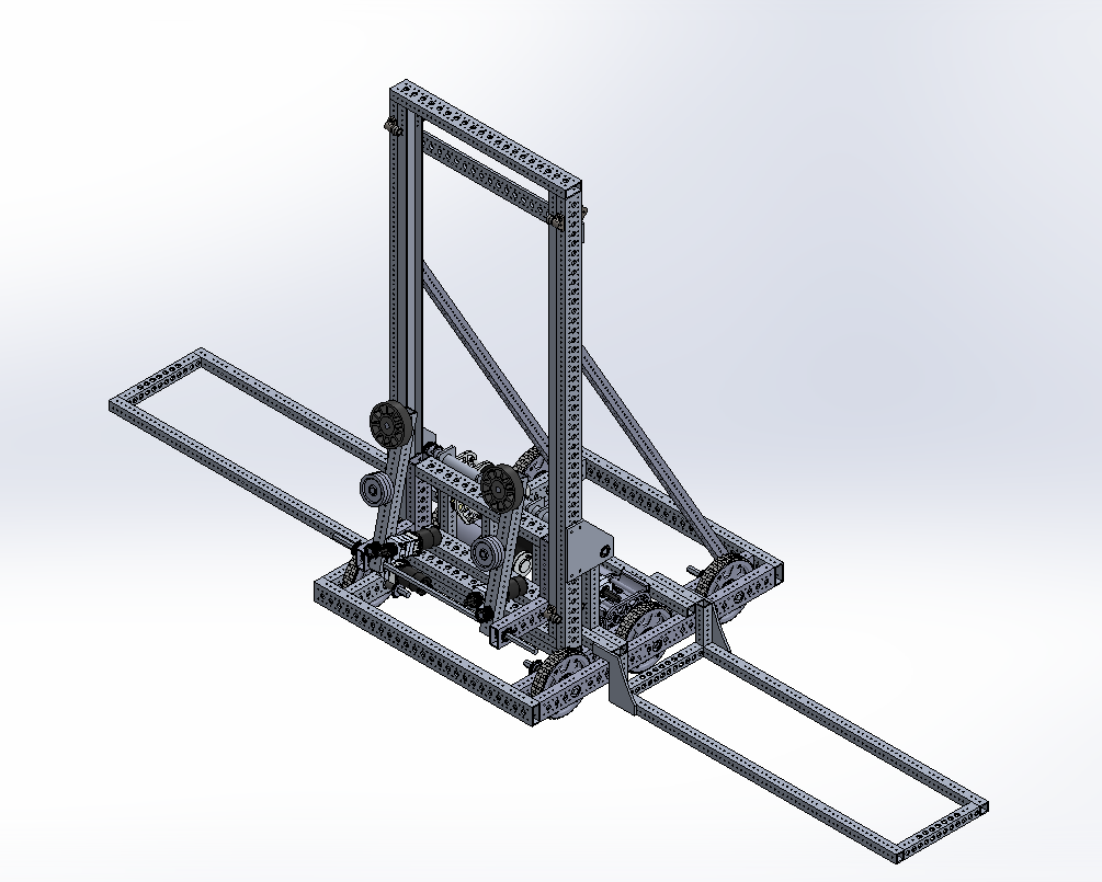
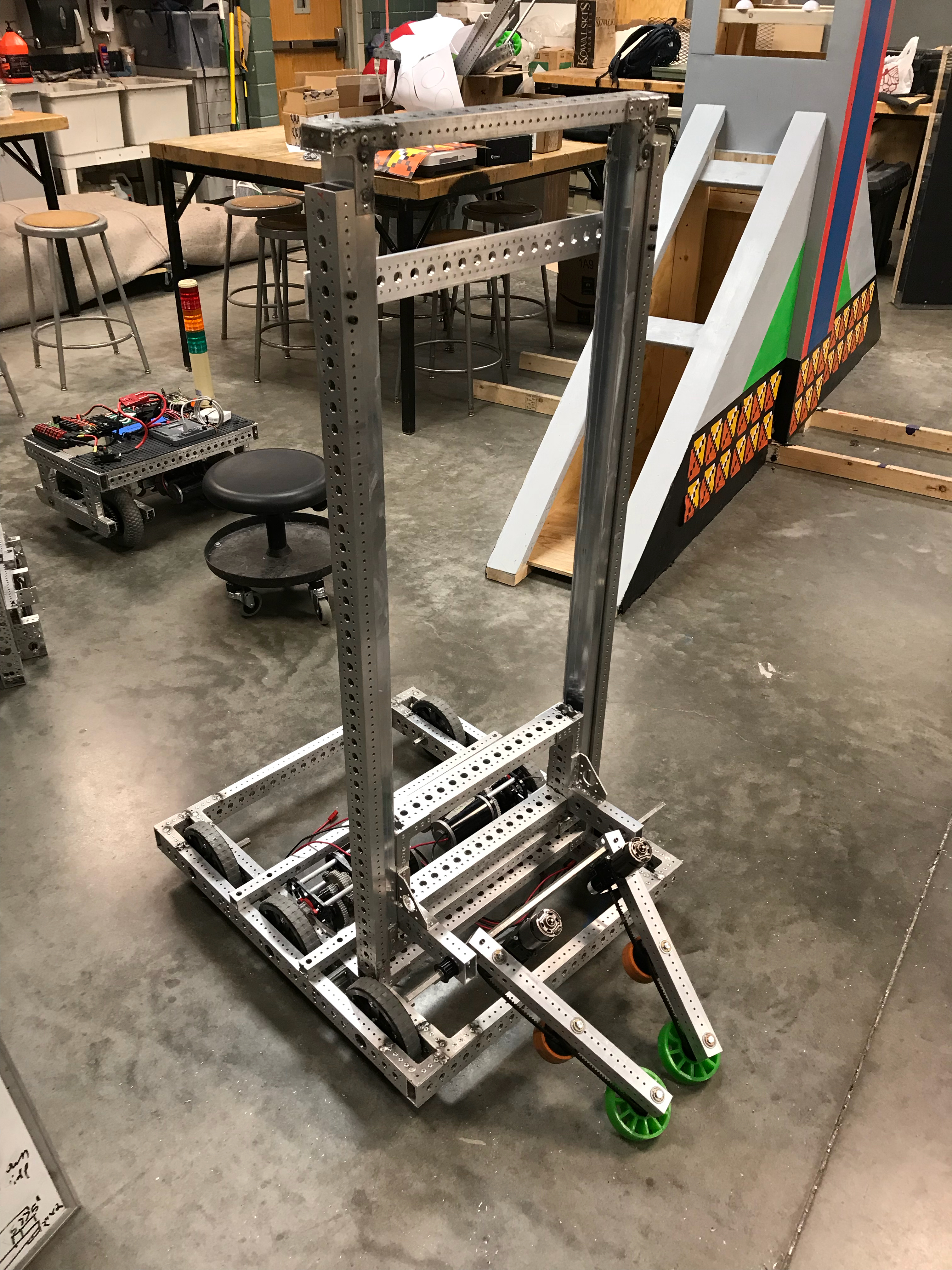
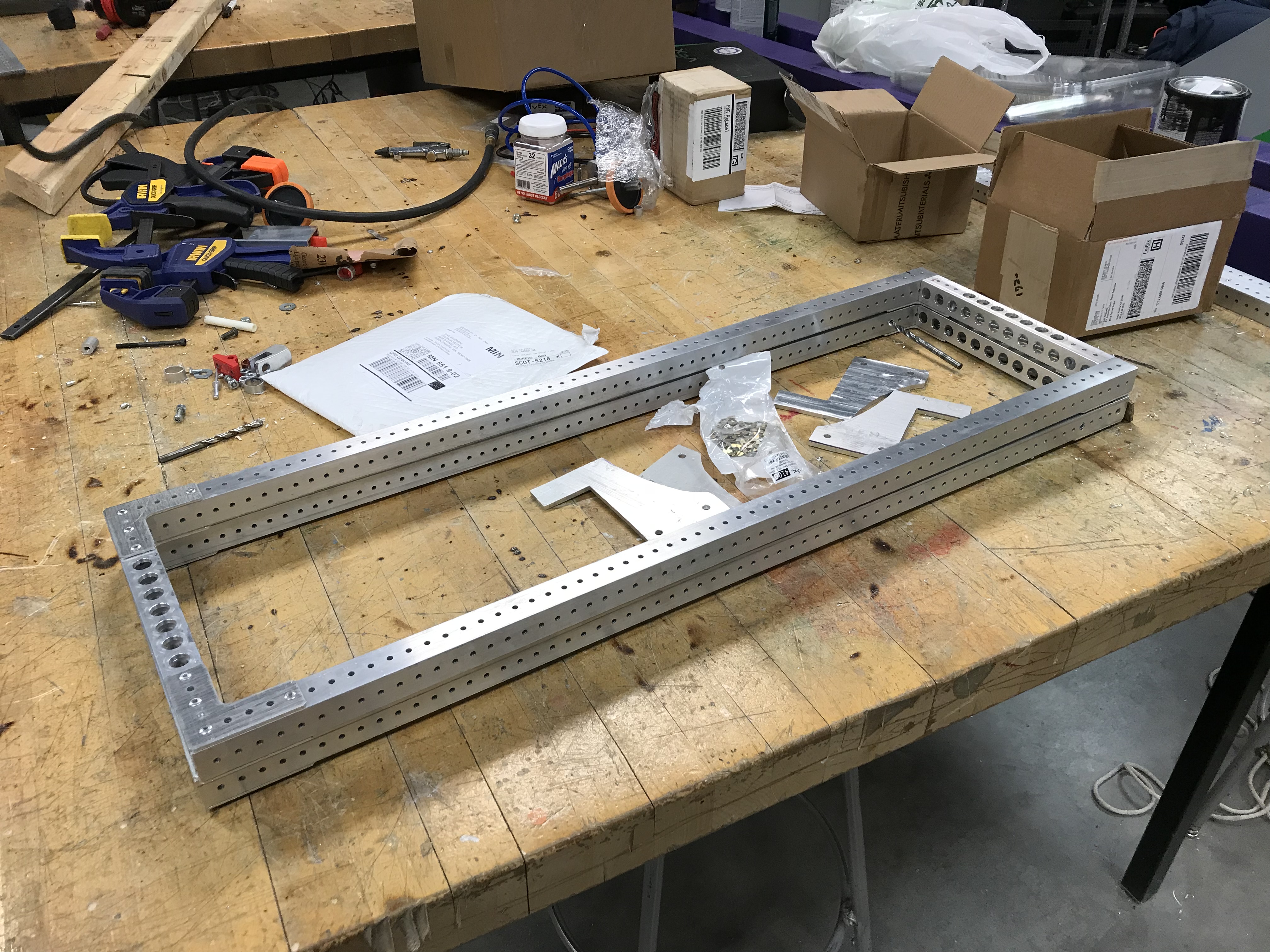
After a few weeks, we finally got most of the parts back from CEM, or rather enough for us to almost completely finish a practice robot, and make many of the subsystems for the competition robot. CEM is an amazing sponsor, and even though they are really far behind on all of their orders, they still put us at a high priority and got us parts as fast as possible even though this was the most parts that needed to be machined by the team, and even though we scratched their door (sorry Eric!). Huge shoutout to Eric, Greg, Tim, Steve, and Steve. Thanks for making this season possible! We assembled our frame, mounted the elevator uprights, and got it welded by Tim. We decided to go back to the frame/welding style we used back in 2016, where we riveted plates onto the joints, and then just welded the plates onto the frame. We did this because last year when we decided to fully weld the frame, it came back very warped, and it was a pain to do/make it happen. This year it was a breeze, Tim (hopefully) had a fun time welding, and the frame was not warped whatsoever. The frame is amazing! This method is by far a lot better than what was employed last year. We also welded together the second stage of the elevator, because that will be bearing tons of weight when we climb. This was done very well, and in Tim’s words, “It ain’t going anywhere.”

In addition, CEM invited our team to come and watch Steve run our parts through the CNC mill. It was really fun, as we watched our parts get drilled, and we got to talk with Steve about machining and whatnot. It was a great opportunity, and Eric even invited us again so that more rookies could go next time. We are grateful for the offer.


Another side note includes frustration with Fastenal and rivets. Long story short, we are running out of these rivets, but we will have enough for the time being. We will be getting an order of 500 on Monday, which will be plenty for assembling the competition robot.
After finally being able to use our parts we machined, we realized that the parts with the retaining ring in them were amazing. They shafts were so easily assembled, everything fell into place, and we do not have to deal with those stupid shaft collars or taping the end and putting a screw in them, for most of the parts. For example, we do not have to deal with putting something like a shaft collar on inside of the frame for the drivetrain: now it is just a retaining ring. This is definitely something we should pursue more in the future.
Our new goals for this weekend include completing the practice robot (what we can do at least), finishing the practice robot electrical, and finishing all of the competition subsystem parts that we have in our possession. We hope to get everything welded for the competition robot before next weekend (preferably Thursday), so that we can finish our competition robot before the driver’s test. During next week, we hope to be incorporating sensors, such as limit switches and proximity sensors, and a carriage brake into the practice robot so that we can move it into the competition robot.
Drive Train
After receiving the welded frame from CEM, we went to work on adding the wheels and the gearboxes for the drive train. After successfully putting on four wheels, we confirmed that the frame was not warped, as every wheel was touching the ground at all times. We were incredibly happy about this, especially since this was an issue last year for us. We then continued to mount the gearboxes, and after a lot of spacer placement skills, we successfully put on all of the wheels on our drivetrain. Since we decided to do our sprockets differently this year, we had absolutely no issue with the two gearboxes hitting each other when trying to put both of them in, contrary to the issues we had back in 2016 and 2017. These are a lot easier to modify/fix if need be. We also had some rookies add the churro supports in between the frame for making sure the frame does not destroy itself when triple climbing. After drilling too many extra holes and sanding down one churro, this job was finished. Our goals for tomorrow include putting on the sprockets, and connecting every wheel to its corresponding gearbox with chain.
Elevator Assembly
After getting the second stage welded, we set out to finish putting together the carriage that goes inside of the u-channel. We also learned about tolerancing again today and what happens when you do not build them into your parts. Yay! We got this finished today, but we had a few issues with putting it into the second stage, and a ton of binding issues. A mistake we made was almost fully assembling the carriage outside of the second stage. Since the second stage is welded, we cannot take the top off to insert the second stage, like in the prototype. We fixed this by taking out the rivets and assembling the carriage inside of the second stage. We also had to shave down the bars connecting the two halves of the carriage, because they were slightly too big for the second stage (yay tolerances). After this, we noticed that the carriage would bind and get stuck a lot, and also make a wretched sound as it traveled. We fixed this by adding white lithium grease to the outside of the bearings, and inside of the u-channel and the sides of the carriage. This helped a ton, and now it slides like a car down an icy hill. Hopefully we will be able to finish assembling/attaching this to the practice robot (using the 3D printed bearing blocks temporarily until we get the steel ones from CEM) before tomorrow ends (Grant wants to go home early on Sunday). We will also plan on making considerable progress on the drum tomorrow/Sunday.
Active Intake
Since our usage of belts and retaining rings, this one bar far the easiest part of the robot to assemble. We even got our competition ones built! The belts are incredibly light, easy to use, not as messy, and incredibly convenient. This is also something we should pursue more in future seasons. We also added this subsystem onto our carriage today, and it went on smoothly due to the retaining rings. These rings also allowed us to quickly adjust the active/take it on and back off again as we put the active on wrong around 4 times. Each bar has a ½” slotted hole, so it can rotate around the hex shaft. It uses a 10-32 bolt as a pivot, which will eventually be controlled by a pneumatic, like on our prototype. Our goals for this weekend will be to add the pneumatic cylinders to the active, and create hard stops so the motor leads do not kill themselves.
Butterfly
We started assembly on the butterfly for the practice robot. Our progress for this is shown below. We will be making a set of wings for the practice robot, but not actually using them until we get them welded by Tim; otherwise, we risk breaking them. Our plan for tomorrow is to finish assembling the wings, make sure they fit on the frame, and get them ready to be welded for next week.
Programming
Quite a few interesting events have occurred since last blog. This includes us creating a legitimately working implementation of Pure Pursuit. Here are videos demonstrating the progression of Pure Pursuit.
One of our first semi-successful tests (with voltages)
Two tests at 3 ft/s and 6 ft/s (with PIDF)
Pure Pursuit works by maintaining left and right wheel velocity ratios. Each ratio will create a specific arc. A set voltage ratio does not necessarily mean the velocity ratio will be the same. It is clear from the video that PIDF is much smoother.
Pure Pursuit Tuning
After wheels go the required velocity, there are many possible steps to tune Pure Pursuit. This includes many options, including:
- Scaling the lookahead distance based on latitudinal velocity of the robot with respect to the path
- This should fix oscillations at high speed when the robot is on a path
- Dynamic speed based on curvature (might have a second instance of Pure Pursuit running to look further ahead to when speed should slow down)
- Makes it so robot can maintain precision on curves by slowing down
- Dynamic lookahead distance based on curvature
- Should avoid slipping on harsh turns by making turns less harsh
Potentially, these can be combined.
Encoder Installation
The encoders on the drivetrain are the most essential sensor on the robot, closely followed by the NavX. By using encoders on the drivetrain, the programmers know precisely how far the robot has moved. This allows the programmers to fix bad build quality with good code quality, as seen with Voyager. Voyager suffered from a disease called Warped Frame Syndrome, which is often caused by too much heat being applied during the welding process. This meant that when equal voltage was applied to both sides of the robot, the robot would veer off in one direction. However, the problem was solved by using encoders to verify that both sides of the robot had travelled the same distance. As a result, the robot would correct itself once it had started to veer away from being straight.
This year, we are moving away from the expensive, cumbersome Grayhill encoders towards the cheaper, smaller, officially supported CTRE Mag encoders. Additionally, rather than putting the encoder on the wheel, we are putting it on an alternate output of the gearbox. Grant, Ritik, Aaron F, Isaac AJ, and Nathan all put work towards the process of installing the encoders. First, they had to find the optimal thickness for the 3D printed spacers designed by Grant. Through trial, error, and lots of sanding, they discovered that the optimal thickness was 0.23”. Then, the team had to use the hacksaw, belt sander, and a piece of sandpaper to thin the 0.375” encoder mounts to 0.23”. Finally, Ritik got to screw everything in place. Over the course of 2 days, this process was completed for both the practice robot and the competition robot.
Quote of the Day
“Please clap” — Jeb Bush