Plan for Today:
Today is going to be a continuation of yesterday, with prototyping subsystems and implementing new design changes to improve quality. Our goal is to have a vote on final prototypes sometime next week. Although this is actually a little earlier than in previous years, we may be better off with designs this year since there has been enormous progress on all three subsystems over only the last few days; even better, 2/3 of the subsystems have multiple different designs for prototypes. On the programming side, the 2018 code update had been released with the kit of parts on Saturday, and currently is able to run last year’s code on last year’s robot. This is a great achievement so that we may avoid the huge issues we had with the update last year at one of our competitions. This also allows them to start experimenting with the code and figuring out possible strategies and methods of execution for the autonomous programs. Lastly, another reminder to please send photos and videos to Poorva! (you can find her number/email in the weekly emails!)
Active Intake
Today we continued working on our prototype for the active intake. Today, we tried to use pneumatic cylinders to pivot the entire active 90 degrees to ensure that it can start within the frame perimeter. We used two heavy duty bronze cylinders (which was not ideal since we wanted a cylinder that had a stroke length of around 3 inches and the cylinder we used was about 8-9 inches).

Nonetheless, this was still a prototype, so we made do with the ones we have currently and incorporated them into the design. Additionally, we took measurements to begin CADding: the process of making a 3D model of the system to be able to possibly machine it in the future and see it in a way where it will be closer to the final. The prototype is a proof of concept. The actual will use different materials that we are willing to make special for the robot. As we designed the system, we found some limitations. When we CAD the active intake, we can work around these limitations for the final design.
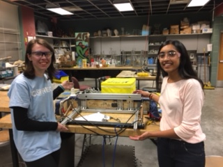
Elevator
We continued work on our prototype that we started yesterday. Today we finished adding the support bars/building the frame of the elevator. We also made considerable progress on the carriage that goes inside the elevator. We decided on having the carriage be 15 inches wide, and have the next stages of the elevator after that, for a total width of 19 inches. Tomorrow we will finish up other parts of the slide, such as hard stops, and start working on the pulley/rope system.


Climbers
Design one: The heart-shaped hook at the top acts like a clip for the bar, so once the robot pushes through the divet in the hook, it will not come off the bar until someone takes it off. There are springs and pieces of surgical tubing to increase speed and strength using the tension of the stretch both when the climber goes up, and when it latches on.

Design two: Of the many prototypes being built and tested, one of these features two pneumatic-powered arms. These arms would close in from either side, effectively trapping power cubes between them. This grabbing mechanism may work together with one of the current prototypes for a lift mechanism to enable us to raise the power cubes onto the switch and scale. Another way that this particular grabbing method may prove useful, is the variability of the attachment to the chassis. Because there is no part that requires rigidity, it could be fixed to a mobile arm that could lift the cube to the desired height, or one of many potential pre-programmed heights.

Video Link to Climber : https://drive.google.com/open?id=1bOR1lz1e7qSTvzaeGoFYrXFw6vYBi9P5
Programming
Today, programmers worked on making Pure Pursuit runnable on Herschel (2017 practice robot) work. We got up to the point in making the robot drive straight, however some input seems to be inverted from what the robot expects; the robot turns in the opposite direction. To fix this issue, we are working on a JavaFX widget for ShuffleBoard. Once completed, this will show us an accurate representation of what the robot is “thinking”. This will most likely look somewhat similar to the already working simulation, but will use data from a robot in real-time.
CAD
Today, the CAD Lead enlisted another fellow team member to CAD in the wheels, drivetrain CIMs, and 2-speed gearbox. We are using 1” thick 6” diameter traction wheels from vex with the traction tire. Not much else happened in relation to the robot CAD, as every other part of the robot is still in the prototyping phase. Our next goal is to have people review the robot CAD so drawings can be sent to our sponsor CEM, who can use their magical CNC to accurately make the thing we want.