Authors: Andrew Georgioff, Ritik Mishra
Climbing
We received and assembled the generator switch (climbing bar) using ladders as temporary supports. This allowed us to more realistically test the climber and roughly test the effect of spacing and weight on the switch angle. Through this testing, we determined that it should not be egregiously difficult to reach a level state.

Above: The current generator switch fully set up.
Balancing Wheels
Today, one of our mentors brought in a home-made flywheel balancer. It looked like this:

The balancer consists of two of these wings:

Each wing is able to clamp around the shaft. Additionally, each wing has 3 holes in the end to add screws to. By angling the two wings away from each other as shown in the first picture, the balancer can compensate for an unbalanced wheel. By adding screws into the 3 holes, the weight of the balancer is increased, which means that it can fix worse flywheels.
Using a jig, we were able to observe the balance of various wheels. The colson wheels were extremely balanced, while the Fairlanes are so unbalanced that the custom flywheel balancer couldn’t help the matter.
Drive Train
Today, since we had two mentors in the room, we were able to send a group up to the machine shop in order to machine all of the drivetrain spacers on the lathe. The lathe is preferred for making spacers (as opposed to the horizontal bandsaw) because the cuts it makes are relatively square. The spacers are made out of McMaster 7767T321 (0.083” thick 3/4” OD steel tube).
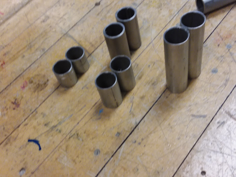
Above: The cut spacers for the drive train
One mistake that we suffered from was that we forgot to order 12 tooth sprockets. By a stroke of luck, we were able to find 8 unused sprockets (they were still in their sealed bags) in the sprockets bin.
Unlike past years, the chain on this year’s drivetrain is actually reasonably tensioned.
We quickly threw on an electronics panel just to see it drive around.
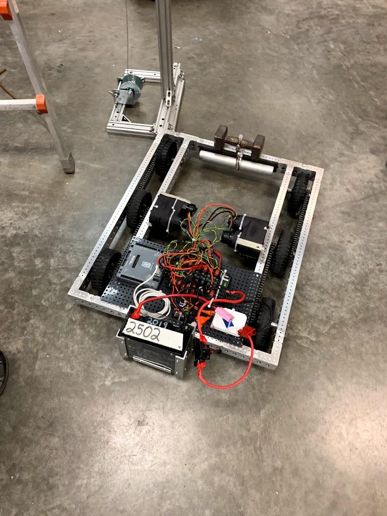
It has driven well so far (aside from strange noises that could potentially be related to bent shafts), and it has been resistant to attempts to push it sideways.
Flywheel Testing
Today, we fired up the flywheel prototype again to run several experiments. One thing we did was to investigate how the compression on the hood impacted accuracy. Interestingly, we found that our results were the best when the compression varied during the shot (.5 in. at the beginning of the hood, 2 at the end of the hood). We also tested how accurate different wheels were by making a scatterplot to visualize the spread. We found that Colson wheels had the least spread, followed by black 80A durometer compliance wheels. We also found that the Fairlane wheels are very unbalanced, as they cause the shooter to violently vibrate at high RPMs.

Above: The scatter plot for the wheels tested. Green – green compliance wheel, black = Fairlane, blue = blue compliance wheel, clear – black compliance wheel.

Above: The scatter plot for the Colson wheels. They don’t expand as much as the other wheels, so it had less compression and as a result shot lower, but the spread was much less than the other wheels tested.
Quote of the Day: “BMP stands for the British National Party” — Danny Georgioff, Non-Engineering Captain