Authors: Andrew Georgioff, Ritik Mishra
Roller Omnis
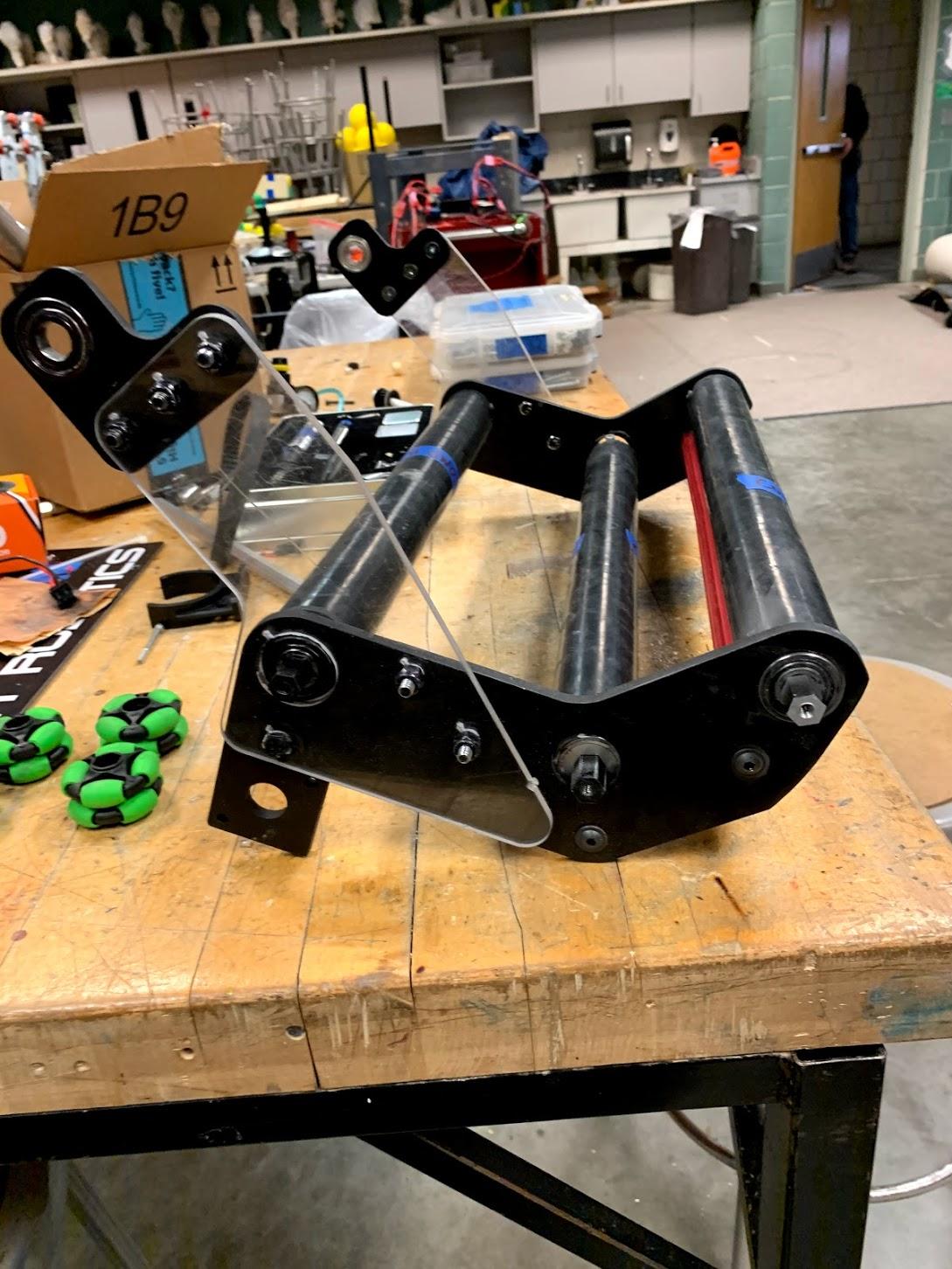
Throughout our testing, we found that the third intake roller bar did not consistently get balls into the hopper. Often times, balls would get stuck between the airpods and the roller. To fix this, we experimented with replacing the third roller bar (1.7” OD) with many 2” wheels. When we replaced the third bar with some omni wheels and a mecanum wheel on the end (to help get the ball unstuck from the airpod), it seemed to work well. However, the balls were getting stuck on the left hand side of the robot, and we only had a right-handed mecanum wheel (which pushes the ball towards the left), so we weren’t able to test the anti-stuck power of the mecanum.
In any case, it was reasonably effective, and could be a lighter solution for the third intake bar, if it comes down to it.
Shooter Calibration
During driver practice today we made several improvements to our accuracy. First, we changed from open loop (voltage) control to closed loop (closed loop on RPM). In a closed loop system, the motor should actively try to reach its target RPM, which should reduce recovery time after each shot and improve accuracy. After we switched to closed loop, we found (through testing) the optimal flywheel RPM for a variety of distances. We used these data points to create a function that should give a good RPM for any distance from 10 to 40 feet. After this was measured, we tested + checked code that is supposed to measure the distance to the vision target using the Limelight. This way, we should be able to automatically set the RPM of the flywheel to make accurate shots on most of the field.
However, one issue that we had was that the closed loop was kinda trash. Specifically, when told to go to a certain RPM, it would only get about 80% of the way there, then quit. This issue was traced back to an inaccurate feedforward value (basically giving the closed loop a guess for how much power to send to the motor). Further testing showed that the spark seemed to be ignoring the feed forward value. Finally, we tried to tell the spark what the feedforward value should have been through the Spark MAX utility, but it didn’t work. When we tried to set the feedforward (kF) to a reasonable value, the utility decided to set it to negative 8 billion instead.
Comp Bot Intake
For the most part, it has been assembled. The outer edges have also been ground down to account for the fact that it extends past frame perimeter on the swing down. However, the third roller may change depending on how testing goes on the practice bot.
Comp Bot Electronics
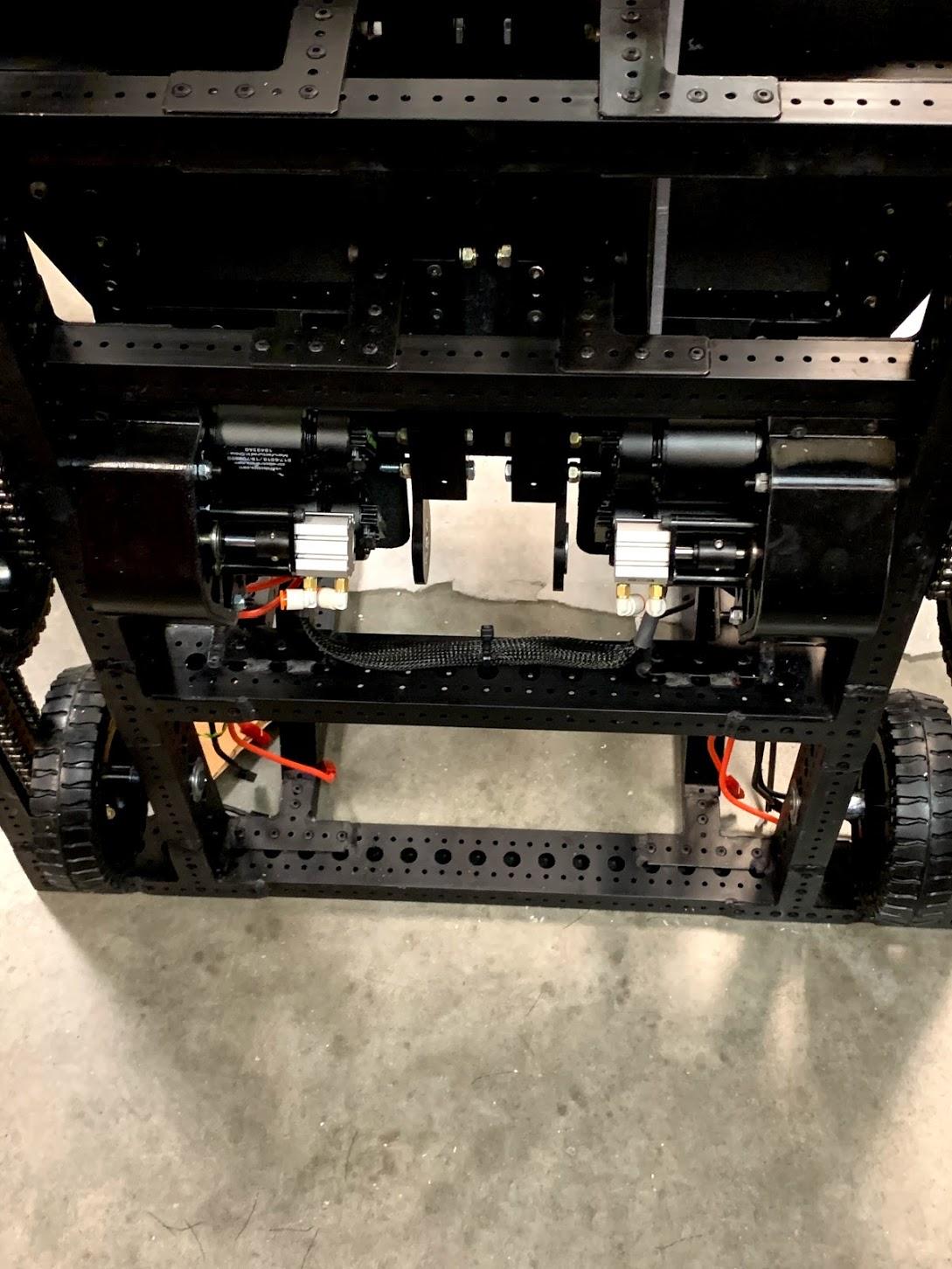
The electronics board has been installed onto the robot (pictured below).

The CANBus for the drivetrain has been wired (pictured below; the CAN wire is hidden inside the snakeskin).
Bumpers
We had to remake our comp bot bumpers due to the fact that the bearing flanges are on the outside of our frame perimeter. The concern is that having the bearing flanges sit in pockets inside the bumpers may not be legal. A solution would be to add small plastic pieces around the frame perimeter so that the bumpers can rest against those instead. However, this requires that we make our bumpers a tad wider. Today, we got the new bumper slats back from a mentor with a table saw (we gave them some spare 3/4” plywood), and assembled 2 of 4 bumper halves.
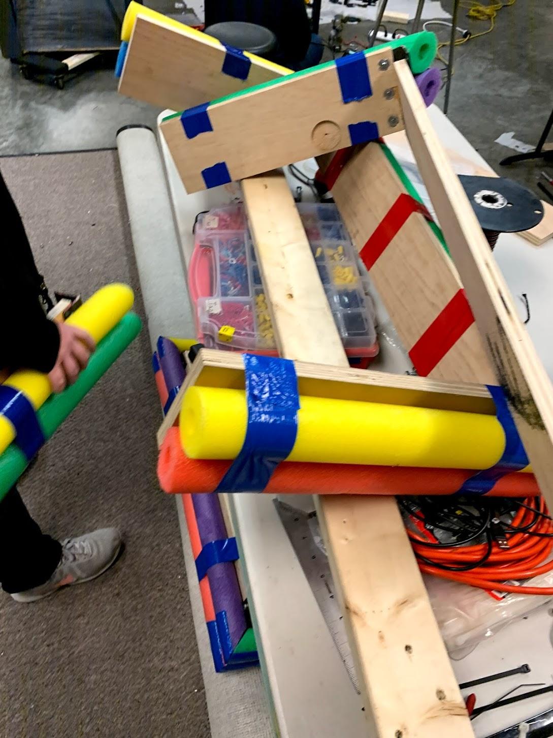
Above: A picture of the bumpers laying on a table
Quote of the day: “Don’t you dare put anything on the blog about heat gun toast” – Isaac Ash, senior engineering captain, veteran programmer, expert polycarbonate bender (not like in avatar)