Authors: Andrew Georgioff, Ritik Mishra
3D Printed Parts
We finished printing our first parts — drivetrain gearbox covers — using our 3D printer from Stratasys. They are made of ABS because it is the only type of plastic (besides soluble support material) that our printer will print. The gearbox covers will help to prevent unwanted debris from entering the gearbox and damaging the gears.
We also printed hex spacers to center our flywheel (we were previously using duct tape). One problem that we encountered with the hex spacers was that the hex bore was modeled in CAD to be exactly 0.500” across the flats, when it should have been a tad larger (i.e 0.505” or 0.510”) in order to slide more easily onto the hex shaft.
Finally, at the end of the night, we started to print a limelight mount and NavX cover. These should be done tomorrow.
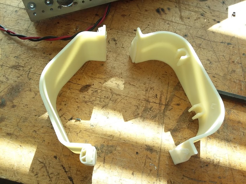
Above: A set of gearbox covers after being 3d printed. Note that there is still some support material attached, which we removed before attaching them to the robot.

Above: A set of gearbox covers installed onto a gearbox.

Above: The limelight mount and NavX cover, starting to be printed.
Welded Parts
Today, we brought our competition robot chassis and climber hook to CEM so that they could get welded together. We got both back today. The climber hook was assembled onto the climber, and some minor changes (mostly cosmetic) were made to the competition robot frame before it went to get anodized.
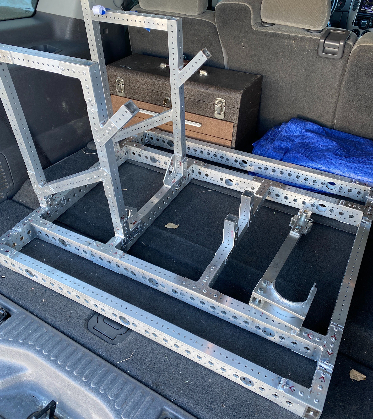
Above: The competition robot frame and climber hook sitting in someone’s trunk after they were welded.

Above: The climber with the climber hook attached
Ball Feeding Hood
There are two large 3D printed “hoods” on the robot. One of them is the shooter hood, which should arrive by tomorrow night. The other is the lower hood, which guides balls from the hopper into the shooter wheel. We received and installed this part today. The square hole in the side of the part is meant to have a 1×1 raptor bar pass through it for the purpose of support. However, since the angled shooter support bars were not assembled in the right position (relative to the CAD model), we had to make our own L bracket in order to attach the rear hood support bar to the robot. In the CAD model, the support bar was designed to be coplanar with the shooter’s support bars, allowing us to use COTS gussets instead.
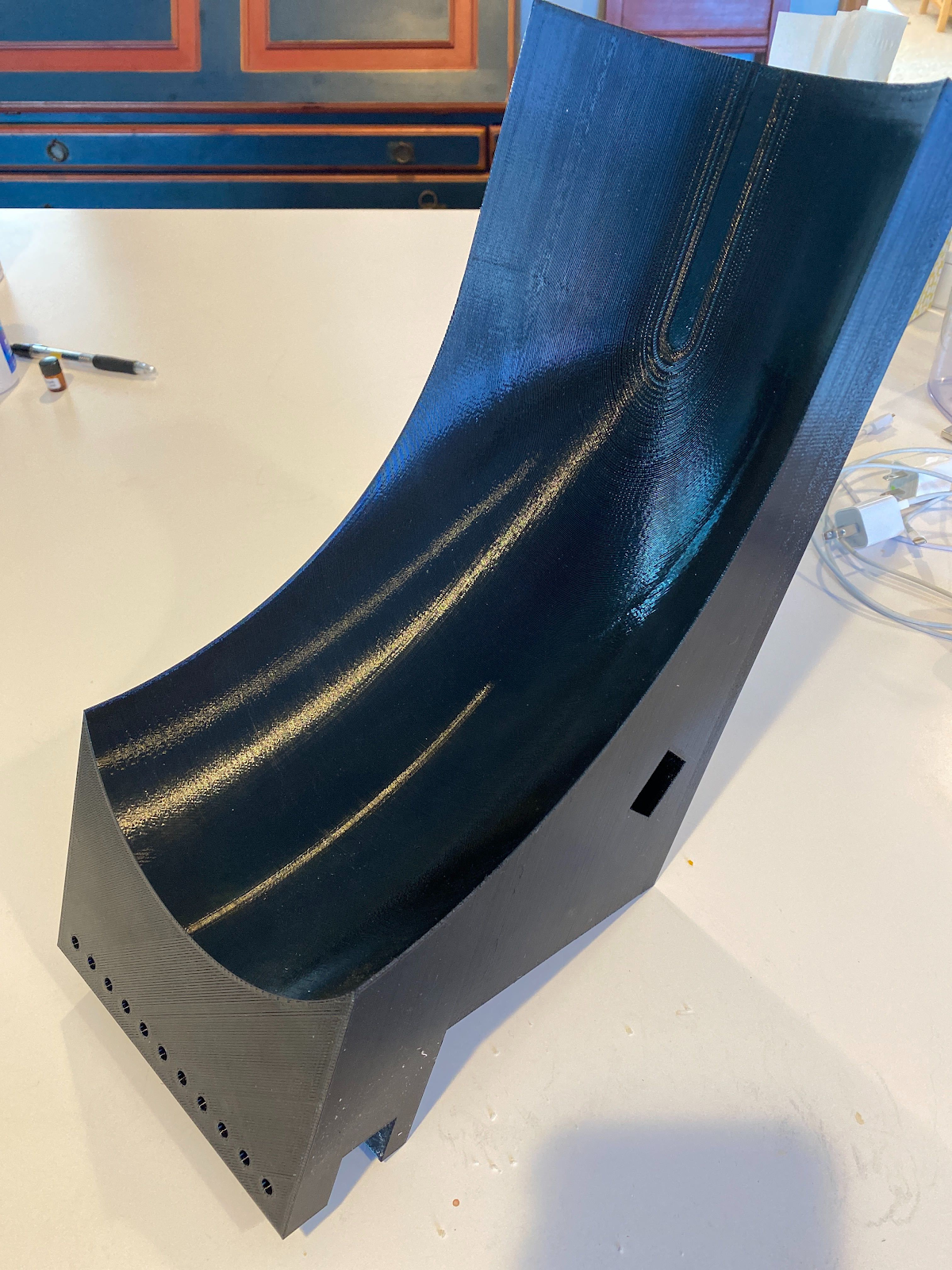
Above: A picture of the lower hood on its own

Above: A picture of the hood on the robot
Intake
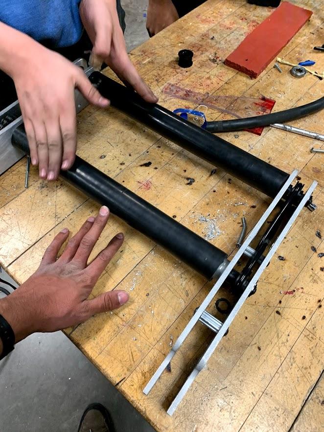
Today we added chain to our intake. Originally, we were going to use timing belts rather than chain, but we discovered that the belts we ordered were going to arrive late, so we decided to use chain instead to ensure that we would be ready for Week 0 this sunday.

Above: The intake with the belts replaced with chain.
We also installed the rollers on the part that helps guide balls from the intake into the hopper.
Mounting Pneumatics
We mounted most of our pneumatics, including the air tank, compressor and gearbox shifting solenoid, onto our practice robot today. We still have a few parts left such as the pressure gauge, and a second solenoid for raising/lowering the intake.

Above: A picture of the bottom of the robot showing the drivetrain gear boxes (clad in gearbox covers), the air tank, the compressor, and the regulator. Note that these are not on the “bottom of the robot” like the electronics were in the 2017 season. Rather, they are “facing” (i.e protruding) upwards, but just happen to be mounted low on the chassis.
Quote of the day:
Michael Proper: holding up a scrap piece of aluminum plate from the waterjet “What’s this good for?”
Ritik: “Well if you needed a triangle shape you could use the large triangley bit”