Authors: Andrew Georgioff, Ritik Mishra
Introduction
On Friday, we did not have open room because of really bad weather. The school day ended two hours earlier, allowing us to spend more time working in Solidworks on robot design.
On Saturday, the FTC teams that we mentor at the local middle school went to their second qualifier event in Burnsville. Unfortunately, none of the teams qualified to compete at the state championship, but their progress seen since their first event was clear.
In other news, we also received an email back informing us that we would be able to have our robot anodized this year as an in-kind donation. 🙂
Flywheel Testing
We received an improved hood from Stratasys, the design for which was sent on Friday. The new hood design is more rigid and also ejects the ball ten degrees lower (65° down from the vertical to 75°).
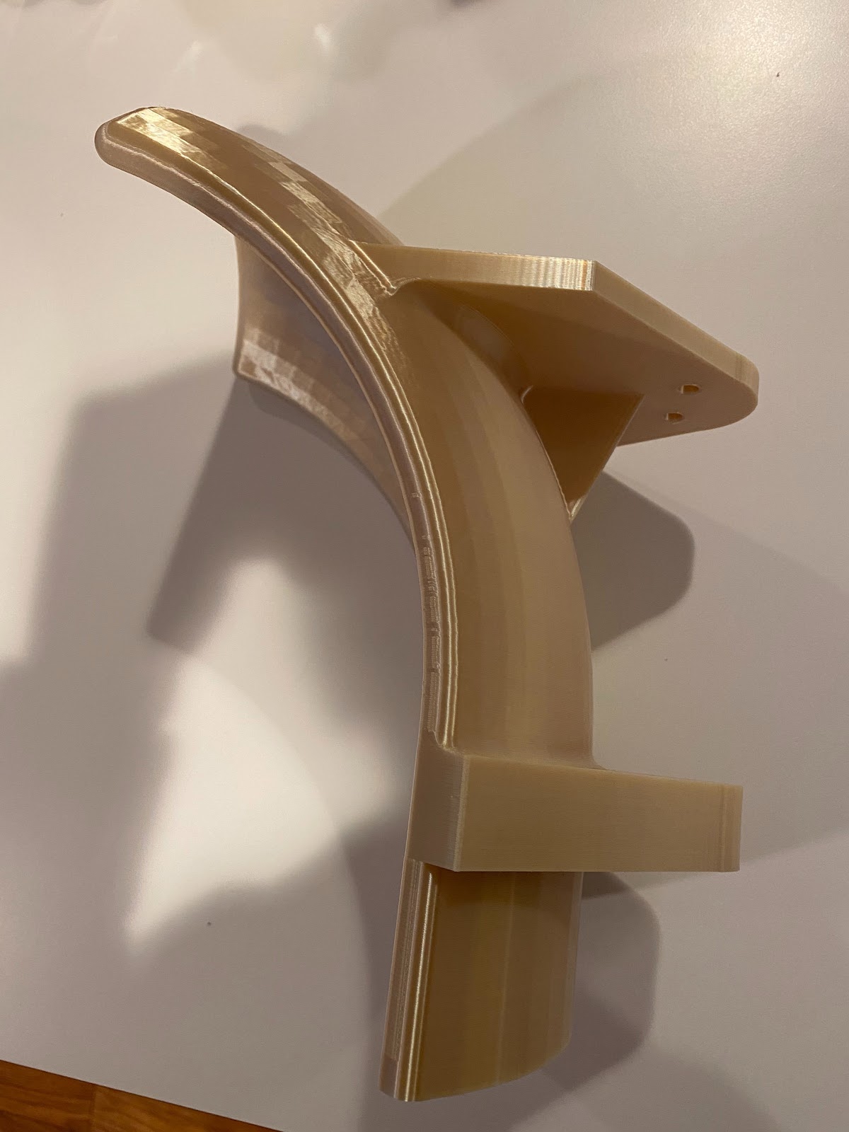
We were able to test shooting with this hood into the actual power port. Sadly, our test rig was not rigid (and in fact it slid around the floor quite a bit), meaning that our accuracy results were not representative of the maximum ability of the shooter. The shooter also vibrated itself apart on multiple occasions, losing shaft collars, retaining rings, and even entire bars if we ran the shooter at top speed for too long.
For comparison, we also tested the double flywheel. The rubber shock mount and overall high construction quality made this prototype significantly more robust than the single flywheel. This comparison informed the flywheel vote we made tonight.
We also tested a simple straight hood to see if we could abuse backspin to make really close batter shots. Surprisingly, it worked!
Drivetrain
Today, two drivetrain gearboxes were assembled which is enough for one robot. Two more will need to be assembled for the second robot.
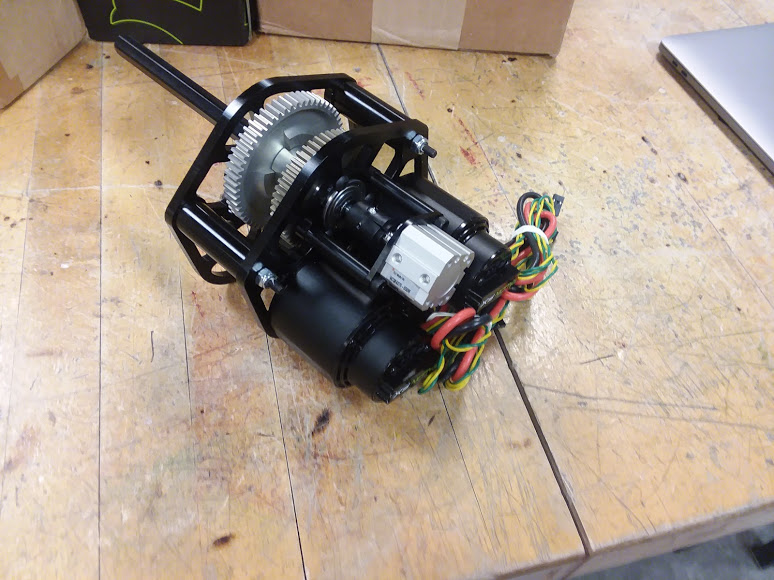
Surprisingly, the pinions were a press-fit onto the Falcon splined shaft.
Additionally, the bearings were added to the practice bot frame. Traditionally, we build our practice bot first so that we can make all of our mistakes and iron out the assembly process before we build the competition bot.
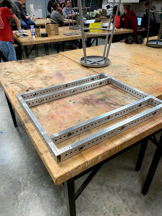
One thing that we did differently this year is that we welded the inside corners of the drivetrain. We will see if we experience excessive warping soon
Flywheel Voting/Design Review Meeting
Today, we voted on whether we would use a single flywheel or a double flywheel shooter. We postponed the flywheel voting to today so that we could test the two prototypes on the power port. After testing each for a while, the team ultimately voted for single flywheel for our final robot design.
Here are the pros/cons that we saw in each prototype
Single flywheel
- Less accurate because of intense vibrations
- Probably accurate if it is rigid
- Consistent horizontal spread
- Vertical spread can be refined probably
- Backspin is probably going to be more consistent
- Buy half as many wheels
- More limited in adjustability
Double flywheel
- If you touch one wheel before another, you completely change the whole shot
- More shot options (backspin, faster, etc)
- Can work to shoot balls down the field
- Works better if you make one wheel slower than the other (aka emulating the effect of a single flywheel with a hood)
- Compression varies a lot more (wheels are not flat and they are the only thing that provides compression)
After this decision, we began our design review meeting. At this meeting, we discussed implementation details for several robot mechanisms.
Flywheel
A big issue with the single flywheel design in its current state is the intense vibrations that it has. Several ideas were brought up to manage the vibrations, including
- Compliant mounting, similar to what was done on the double flywheel prototype
- Special bearings
- As it turns out, there are many kinds of bearings. The “default” kind that we use most often are radial ball bearings, although others are better suited for other kinds of loads.
Another thing that was brought up was the recovery time. In order to minimize the recovery time, we came up with a variety of ideas
- Multiple motors
- A very good point was brought up regarding using multiple NEO brushless motors. Specifically, due to how brushless motors work, we may only get a 60% torque boost (instead of 100%).
- A large flywheel weight
- FIRST Capital was using a lot of weight on their flywheel (6 Fairlanes and a 2 lb mass?)
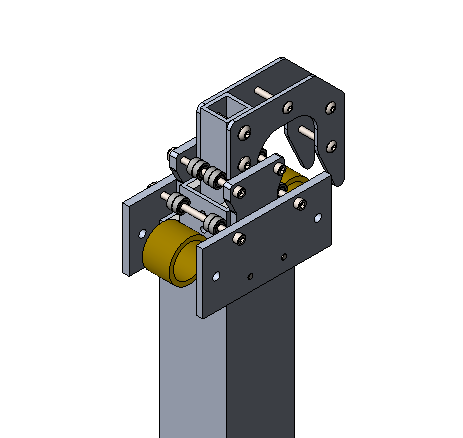
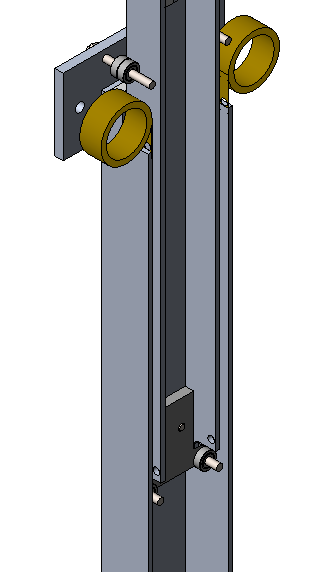
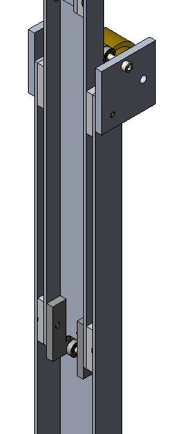
Climber
The current climber design is a 2-stage cascading telescoping arm with a hook at the top. One concern that was brought up is that the strength of rope is reduced when it is routed around a sharp bend (which will be required given the space constraints). Another concern is that compared the system will not be that much lighter than a comparable 80/20 setup, although it does have the advantage that the stages are nested as opposed to staggered. This is advantageous because it reduces the amount of torque experienced by the climber during a climb.
Quote of the day: More power is more better – Ryan Mikol, Strategy and Scouting Lead discussing motors