Drivetrain progress: Parts, CAD
Today, some significant progress was made on the drivetrain!
CAD
Today, a significant CAD update was made. Specifically, the wheel wells were widened from 3.25 inches to 3.5 inches. This will allow us to use the brackets we already have laying around for robot assembly.

The distance between the green lines (the wheel well width) is measured to be 3.5 inches in the CAD. The holes on the bracket at the bottom left align perfectly with the holes in the frame
Also, two insignificant CAD updates were made. First, the drive gearboxes were defeatured. “Defeature” is a tool in SOLIDWORKS that allows one to take a complicated part or assembly (e.g a gearbox, which has unimportant details on the gears, motors, shifter, etc) and simplify it by only taking the necessary geometry (e.g the approximate cylindrical shape of the motor). By getting rid of all of the unnecessary details, the performance of SOLIDWORKS when browsing the CAD is mildly improved.
Second, the chain on the drivetrain was roughly CADded. This way, we know where the chain will be so we can avoid accidentally putting anything in its path.

Look at the lack of all those features! No teeth on the gear, no wires on the motor, no pockets on the gearbox plates, and no rivets on the chain between the wheels!
Parts
Today, we received several parts from VexPro. These parts included
- Drivetrain gearboxes (all 4!)
- Roller chain
- Bearings
- It turns out these were the wrong bore (round bore instead of hex) so we will probably need to return them
- Hex shaft stock
From the hex shaft stock, we cut all 8 of our drivetrain axles (4 per robot). We also gathered together 16 L brackets and 16 T brackets we had sitting in overstock since the 2019 season.
Once the drivetrain rails are done being machined by CEM, we will probably go down there with some rivets and our brackets, rivet together the drivetrains, and then tack weld the drivetrain together. Tack welds are preferred over full welds due to the potential warping that the heat from the welder may cause.
We have started assembly on our drivetrain gearboxes, but since we bought 12t pinions instead of 11t pinions for our Falcons in the preseason, our gearboxes cannot be 100% assembled quite yet.
Caterpillar
What is a “caterpillar”?

This is a caterpillar
This is the caterpillar we are trying to make.
Single Flywheel Shooter
Today, we wanted to test shot consistency with our Single Flywheel shooter. Ideally, we would have used the power port we have recently received, but we were unfortunately unable to because of space constraints. The commons were being used for an event, the hallway was too small, there was wind in the parking lot, and the ceiling in the robotics room is too short to fully assemble the power port.
Before we could test, we had to first fix the shooter. It was bent at all sorts of funny angles, so we made sure to loosen, square up, then tighten everything. We also relocated the two base bars to be below (rather than beside) the shooter in order to stop the flywheel and hood from bending apart as much.
We ended up deciding to only run at 50% speed and shoot at the back of the black storage cart. We tested whether or not having the anti-flex metal bar on the shooter hood made a difference in shot consistency. By putting a piece of masking tape down on the cart wherever the ball hit it, we were able to see that it didn’t make much of a difference. We ultimately concluded that the metal bar did not make an appreciable difference in single shot consistency.

This is our scatter plot. The tapes labeled “N” were places where the power cell landed when they were shot with no bar.
After our experiment with shot consistency, we tried to make a caterpillar by shoving a bunch of balls through the shooter with some wood blocks near the end to push them up into the flywheel. It did not go that well.
Sadly, it got jammed.
L tunnel – Return to v1
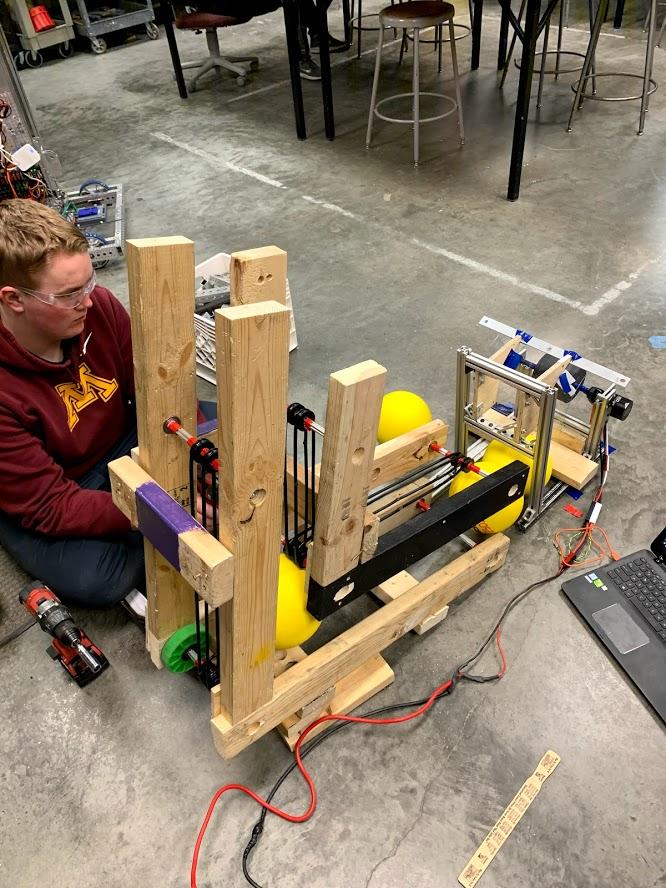
Today, we went back to working on the v1 version of the L tunnel that was made of wood. When open room started, we changed it to fit the power cells instead of the 2016 boulders. Unlike the boulders, the power cells seem to be significantly grippier, making it a little harder to spin the polycords while keeping the ball still.

Combining the two
Since the first, jerry-rigged guide to push all the balls through didn’t work too well, we tried to use the L-tunnel to feed balls into the flywheel. Sadly, that didn’t work too well either. There was too much dead space for the ball to just sit and jam everything right below the shooter wheel.
Finally – a Caterpillar?
Eventually, we went back to just using a jig to push all the balls into the shooter. This time, we put some more effort into it. It worked comparatively well.
2nd Drivers station
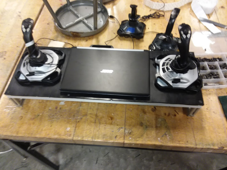
We finished assembling our second driver station today. Earlier, we had both found a driver station frame built out of 80-20, and marked out a section of plastic salvaged from our 2019 field elements that would become the top of the driver station. Today we cut the plastic, drilled holes in it, screwed it into the 80-20, and put velcro on it so we can securely attach our joysticks and laptop to it. Previously, we only had one driver station which was large and difficult to carry around, so this second smaller driver station will be easier to transport to demos or other events that we drive robots at.
Quote of the Day: “Are you gonna bean them with dodgeballs?” — Isaac Ash, senior engineering captain, during a discussion about whether or not the robot could fit through the door with bumpers on (it can’t).