Introduction
Today, we started designing and building prototypes. There are a lot of really cool ideas. If you have ideas that aren’t being made right now, you can come to open room, get a few people together, and start building it. If you are building a prototype, PLEASE SEND A PICTURE OF IT TO POORVA. Additionally, always remember to SIGN IN AND OUT EVERYDAY. If you don’t sign in or out, you won’t get credit for the hours that day, and in order to letter, you need to have a certain number of hours in the room. Today we got a brand new Drill Press donated by CEM. It is a lot bigger and stronger than our last one. Due to the size of this new drill press (it towers over most people when it sits on the counter), there are going to be some new safety rules that will need to be followed when using this tool. There will be an email sent out containing all the safety rules. We also talked about the use of retaining rings instead of shaft collars. We will probably look into this when designing subsystems in CAD.
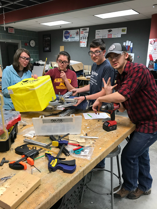
Active Intake
A portion of our team started to work on a way to pick up the power cubes. The team looked at modeling the intake of robots from 2015 which also involved picking up square-shaped objects. One member found the video: https://www.youtube.com/watch?v=jH4n1X1Oz7c of simbotics intake and the team decided to look into how to make it. This intake was chosen because it actively pulls the blocks in and it does not require actuating the claw portion of the design. The team started modeling a design very similar to this using 80/20. The design is mostly finished (see attached video) except the team has not made a pivot to make it be a completely over the bumper design. The design works really well and can intake the blocks from many directions. The only issue with the design is that the 80/20 loosens but that will be fixed by making a more accurate model. The team hasn’t decided what will be happening tomorrow but it will be some kind of testing with improvements and adjusting how the design moves. We will also begin the process of CADing the design.

Heres a video showing our prototype in action!
https://photos.app.goo.gl/wkYT4Z7SKhd1Hnl93
Elevator
Today we started working on our first lifter prototype. Essentially, this will be an elevator, very similar to 1114 and 254’s robot from 2011, Logomotion. For prototype purposes, we 3D printed our own bearing blocks before today started, so we were ready to go.

We achieved putting together the basic parts of the slide components. All bearing blocks were mounted to the “2 by 1” aluminum tubing and c-channel. Tomorrow our goals are to put together the two slide pieces and start work on the carriage.
Climber
Since we have multiple people working on each of the other subsystems, we also had a group that worked on creating a climber to hang on the metal bar on the scale at the end of the match. This climber uses principles of climbers from 2016’s game since the round metal bar on the scale is essentially an almost exact copy of the bar from the game two years ago.

The heart shaped hook at the top acts like a clip for the bar, so once the robot pushes through the divet in the hook, it will not come off the bar until someone takes it off. There are springs and pieces of surgical tubing to increase speed and strength using the tension of the stretch both when the climber goes up, and when it latches on.
Programming
Today programmers were very productive and worked primarily on migrating code from UpdatedRobotCode2017 to RobotCode2018. We are already at 76 commits and are starting the season strong. Prime examples of migrated features were auto-shifting and the many drivetrain components. We also worked on some new features. Autonomous is very important, so there is a lot of possible work that can be put into this. We started out by planning how the robot would maneuver based on starting game configurations. There are 4 (RR,LL,RL,LR) scale-elevator configurations and 3 (L,C,R) robot configurations. This will make us have $latex 4\cdot3=12&bg=ffffff$ total configurations to have to worry about. Navigation on the desired trail is made easier by the Pure Pursuit algorithm. All code in the simulation used to help develop Pure Pursuit has been ported over to RobotCode2018. However, it has yet to be properly tested on a tangible robot.
Pure Pursuit
PurePursuit is a common way for robots to go between multiple waypoints in a smooth path by traveling on arcs of circles connecting goal points to the robots current position. There is a working simulation made for Tank Drive, and an example video demonstrates it in a real environment. Along with several others, a large challenge with Pure Pursuit is maintaining optimal velocity and acceleration, such as to be kinematically possible for the robot to keep on the required path. This will continue to be a large area of learning for the programmers. If you are more interested in contributing to Pure Pursuit or knowing how it works, a useful list of resources are as follows:
- Paper on PurePursuit
- Robot Kinematics
- End requires knowing about Affine Transformations
- MIT example Pure Pursuit (w/ acceleration) implementation
Additionally, edX has a course on Robotics: Fundamentals which explains a lot of maths related to Pure Pursuit and developing an awesome robot.

CAD
Today, the CAD lead began work on designing the 2018 robot frame in Solidworks. There are several design decisions that he made that you, dear reader, should consider making in the design of your own robot frame. Tomorrow, the CAD Lead wants to get some other team members to insert the 6” Vex Traction wheels, 2-speed gearbox, and 4 CIM motors into the CAD.

Notable Design Decisions
- Notice how the back bar runs the entire length of the frame, rather than being in between the sidebars. This guarantees that if the robot rams into a wall really hard, the sides will not pop off.
- Notice how the center bearing hole is “dropped” relative to the center of the bar. If you have a 6 wheel tank drive, and don’t drop the center, your robot will not turn smoothly. Additionally, it will make funny noises when turning. Therefore, if you want a good robot, you should drop the center wheel on your 6 wheel tank drive.
- Notice how the other 2 bearing holes are slightly offset from the constant pattern created by the middle 0.5” holes. The distance from the 2 bearing holes and the center bearing hole was calculated such that the chain will be tensioned properly when wrapped around the sprockets. He used 2 different equations; one was from Chief Delphi, while the other was provided by a captain.
How to Calculate the Number of Chain Links Needed
When designing something with sprockets, one must keep in mind that you can only have whole chain links, and that half links are extra work. If your chain is loose, it is prone to slipping. It pays to place your sprockets such that a nearly whole number of chain links are required such that the chain is nice and tight. Below are some methods of calculating the number of chain links needed between 2 sprockets. Be warned that if Cis odd, you will require a half link.
Cool Kids Method (Travis’s Method)
$latex \frac{C}{2}= (d+\frac{c_\text{pitch}}{2}) \cdot \frac{8}{3}&s=3&bg=ffffff$
In this equation, $latex C&bg=ffffff$ is the number of #35 pitch links you will need, $latex d&bg=ffffff$ is the center-to-center distance between the sprockets, and $latex c&bg=ffffff$ is the pitch circumference (calculated from the pitch diameter) of both sprockets.
Chief Delphi Method
$latex C=\frac{2E_4}{E_1} + \frac{E_2}{2} + \frac{E_3}{2} + \frac{\left(\frac{E_2-E_3}{2\pi}\right)}{\frac{d}{E_1}}&s=3&bg=ffffff$
In this equation, $latex C&bg=ffffff$ is the number of chain links you will need, $latex E_1&bg=ffffff$ is the chain pitch in inches (for #35, it is 0.375 inches),$latex E_2&bg=ffffff$ is the number of teeth on one sprocket, $latex E_3&bg=ffffff$ is the number of teeth on the other sprocket, and $latex d&bg=ffffff$ is the center-to-center distance between the sprockets.